 ACP's electronic system (ACPE) is composed of four functional blocks : DC/DC converter, control unit, monitoring unit and drive unit. The structure has two frames and a base plate, both made of aluminium alloy.
ACP's electronic system (ACPE) is composed of four functional blocks : DC/DC converter, control unit, monitoring unit and drive unit. The structure has two frames and a base plate, both made of aluminium alloy.
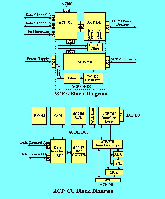
The first frame contains two parallel printed circuit boards (PCBs), one for the control unit (ACPCU) and one for the drive unit (ACPDU). The second frame, which has an integrated top plate, contains the monitoring unit (ACPMU) PCB and the components for the DC/DC converter block (see figure above). After final integration the two frames are screwed together; the base plate is attached to the first frame, interfacing with the ACP mechanical main box.
Huygens supplies ACP with three 28 V power lines: main lines MLl and ML3 and protected line PL2. ACPDC's main functions are : (1) to provide MLl input with DC conversion for supplying other electronics functional blocks; and (2) to provide all power lines with EMI filters. Conversion of MLl DC is performed through a circuit that uses in series an SAE, AFC 461 F/CH for transient suppression, an SAE AT 02815 TF/CH for DC/DC conversion and one specific EMI filter to each output of the converter (0, +5, -15, +15 V).
ACPDU drives all the electromechanical devices (electrovalves, heaters, motors) of the mechanical box. DU is galvanically isolated from the drive logic in CU. ACPMU conditions and monitors the temperature and pressure analogue signals coming from the sensors in the mechanical main box. Under software instruction, ACPCU controls ACP's motors, valve6 and heaters (see figure above). For that purpose, it monitors first, inside ACPE, the transfer of actuation commands to ACPDU the flow of digital and analogue inputs from ACPMU. It also monitors all data transfers and synchronisation with ACP external systems such as the Probe, GCMS and ACP's EGSE.
The data are transferred in two directions: (1) from the Probe's Command and Data Management Subsystem (CDMS) to ACP - mainly telecommands, descent data broadcast (DDB) and broadcast pulse (BCP); and (2) from ACP to the Probe - statusword and packet telemetry data (PTD). Synchronisation pulses are sent to GCMS for accurate timing of GCMS and ACP valve actuations during transfer periods. For activating and controlling mechanical and pneumatic components, the command signals generated within ACPCU are sent to ACPDU through a J21 connector. Status and sensor readings from ACP elements are transferred, after conditioning, to ACPMU.
ACPCU's main components are the 80C85 8-bit microprocessor, the 80C37 direct memory address (DMA), a 4.096 MHz oscillator, two PROMs with 8 kbyte memory each, two RAMs with 8 kbyte memory each, a 12-bit analogue to digital converter (ADC) with a sample and hold amplifier (S&H), two 8-channel multiplexers (MUX) and two FPGAs (field programmable gate arrays). In addition, ACPCU contains memory latches, buffers and optocouplers.
The microprocessor uses eight bits for data lines and 16 bits for address lines, eight of which are multiplexed with the address bus. The 4.096 MHz oscillator frequency is divided by one of the FPGAs to provide the non-maskable microprocessor interrupt with selectable clock pulses of 1, 2, 4, 8 or 16 ms. Two other interrupts of the 80C85 are used for BCP pulses every 125 ms (synchronised with the Probe) and overpressure signals. The 12 kbyte program is stored in the two 8 kbyte PROMs. When the ACPE main line (MLI) is powered by the Probe, the 12 kbyte are transferred to the two 8 kbyte RAMs. The remaining 4 kbyte in the RAM serve as data transient memory.
DMA, driven by the FPGA timer, is used mainly for fast telemetry (TM) and telecommand (TC) management. Three of DMA's four request inputs are used for TM/TC data transfer from the 4 kbyte of the RAM to the Probe CDMS. The first two are used for nominal and redundant TM transfer, and the third for TC transfer.
The monitoring signals (temperature, pressure and status) coming from ACPMU are used by the software for controlling the instrument. Analogue signals (temperature and pressure) are multiplexed and converted to digital signals into ACPCU. A total of 15 analogue input lines is multiplexed through the two MUXs. The MUXs output line selection is performed by one FPGA, then the selected signal is transferred via the S&H to the ADC for analogue to digital convertion.
One of the two FPGAs controls the exchange of signals with the Probe (BCP, DDB, TC, TM). It also serves as pump current and speed counter. The other FPGA provides the microprocessor with a timer and a watchdog, and manages the ACPCU and ACPMU multiplexers. This FPGA also controls all the output command signals to ACPDU.
 Back to previous page